


CAV I Grid Code
MSDG Grid Code — Greater than 50 kW and not exceeding 500 kW — Central Electricity Board
Foreword
The purpose of this document is to assist the public to better understand the procedure for application, the requirements of the Grid Code and other related issues regarding Medium Scale Distributed Generation (MSDG).
Any prospective applicant willing to take advantage of the Medium Scale Distributed Generation (MSDG) Scheme is informed that:
- Compliance to this Grid Code shall be mandatory.
- The provisions of the Electricity Act 2005 and associated relevant Regulations shall be adhered to.
- The provisions of the Environment Protection Act 2002, Local Government Act 2011 and Finance Act, and any subsequent amendments, shall be adhered to.
- This Grid Code will be reviewed and updated when the need arises.
Disclaimer
The Central Electricity Board’s “Grid Code for Medium Scale Distributed Generator (MSDG) – Greater than 50 kW and not exceeding 500 kW”, including any periodic revisions published on the CEB website, constitute the minimum technical requirements for the connection of an MSDG of size greater than 50 kW but not exceeding 500 kW to CEB’s 22 kV distribution network. The owner of the MSDG may be required to meet additional requirements to ensure that the interconnection meets all local regulations and is safe for use.
The requirements set in this Grid Code are based on system conditions that may be subject to change. As such, these requirements shall only be used as a guide, subject to in-depth evaluation. CEB reserves the right to revise this Grid Code at any time.
Revisions
- Version 3.0 — September 2024: Grid Code reviewed by CEB; updates performed on applicable capacity, DC-to-AC ratio and Certificate of Installation.
- Version 2.1 — October 2019: Updates on MSDG Interconnection Requirements, Protection Requirements, Typical layout, Harmonics and Metering.
- Version 2.0 — December 2017: Updates on Protection settings, Standards and Circuit Diagram.
- Version 1.0 — May 2016: Initial version; updates on protection, maintenance, administrative procedures, MSDG standards and application forms.
Chapter 1 — Purpose of the Grid Code
This Grid Code describes the technical criteria and requirements for the connection of distributed generation unit(s) of capacity greater than 50 kW but not exceeding 500 kW to the CEB’s 22 kV distribution network.
The proposed capacity shall be the AC power output from the RE installation. Capacity capping on inverters shall be applicable as appropriate.
This Grid Code caters for the connection to the CEB distribution network and production of electricity by the following renewable energy technologies (RETs):
- Photovoltaic (PV)
- Wind Turbine Generator (WTG)
- Hydroelectric Generator
- Biomass-based generator
Note: For the technical criteria and requirements for the connection of MSDG of capacity greater than 500 kW, please consult the relevant grid code available on ceb.mu. For applicants having an existing HT metering supply, refer to Clause 3.1.
Chapter 2 — Connecting MSDG to the Grid
2.1 Connection Process
The connection process follows these steps:
- While an MSDG scheme is open, a duly-filled MSDG Application Form and requested technical specifications must be deposited at the CEB SOLAR PHOTOVOLTAIC SCHEME (HOUSEHOLDS) -MSDG Unit, CEB Curepipe. The processing fee must be settled at the Cash Office.
- Analysis of the MSDG proposal with respect to MSDG Grid Code requirements and the applicable scheme, if any. An Engineering Review / System Impact Study is conducted where required. A network and interconnection survey by district and a joint site visit with all stakeholders is arranged as necessary.
- A Letter of Intent is issued with allocated capacity, along with an invoice for processing fees, cost for network reconstruction, etc. (as applicable). Where network works are required, a cost estimate is sent to the applicant.
- The applicant acknowledges all conditions of the Letter of Intent and settles the processing fee and costs for network reconstruction, etc. (as applicable). If the applicant does not agree to bear costs, the process ends.
- A joint site meeting is held with all stakeholders and the Connection Agreement is signed. The applicant settles the Connection Fee and all other charges as applicable.
- A coordination meeting is held prior to the power cut for scheduling of works. CEB executes interconnection works during the power cut. All other required works are completed and the whole installation is verified.
- The applicant completes the MSDG installation within 12 months from the date the Connection Agreement is signed. Upon completion, the applicant submits a duly signed Certificate of Installation (as per this Grid Code) and an as-made schematic diagram. An invoice for Connection Fee, TTB, modem (if applicable) and testing of CTs is sent to the applicant. The applicant settles all required costs.
- Testing and Commissioning is performed by CEB.
Note: Failing to finalise the MSDG installation and submit the Certificate of Installation within 12 months of the Connection Agreement will result in automatic cancellation of the authorisation.
2.2 Connection Capacity
The maximum capacity of MSDG that can be connected to a Medium Voltage (MV) feeder is termed the connection capacity of that feeder. Different feeders have different connection capacities depending on the electrical characteristics of the conductor used, the magnitude and temporal variation of feeder loading, and the proposed location of connection.
The feasibility to connect any MSDG to CEB’s 22 kV distribution network will need to be confirmed by an interconnection impact study conducted by the CEB on a case-to-case basis. The possibility of interconnecting any MSDG facility with variable power output is additionally subject to the maximum amount of variable renewable energy-based power generation that can be accommodated while maintaining system stability and security.
Capacity allocation rules:
- Applications are processed strictly according to the date/time of settlement of the application processing fees (first in, first out).
- Authorised applications are allocated to the feeder subject to a favourable interconnection impact study.
- Allocated capacity remains valid for one (1) year from the date of signature of the Connection Agreement.
- Failing to finalise the MSDG installation within one year results in automatic cancellation and the capacity is freed for other applicants.
Chapter 3 — MSDG Interconnection Requirements and Safety Aspects
3.1 Interconnection Facility Characteristics
The facility shall have the following characteristics:
- The MSDG facility is connected to CEB’s 22 kV network through a dedicated 22/0.415 kV transformer. Metering is to be performed on the Low Voltage (LV) side.
- For applicants having an HT Metering supply, an inter-tripping and interlocking mechanism shall be implemented between the 22 kV Circuit Breaker (CEB side) and the 22 kV outgoing Circuit Breaker(s) (client side).
3.2 Interconnection Facility Design Parameters
The MSDG shall have the following design parameters and must function and protect itself within the following range of voltages, currents and frequencies on the CEB grid. The CEB LV grid is designed as a TT system.
Table 1 — Design Parameters under Normal Conditions
| Description | Range |
|---|---|
| Statutory Voltage range | 230/400 V ± 6% |
| Short circuit characteristics (excl. MSDG contribution) (1 sec) | 18 kA (50 Hz) |
| Frequency | 49.25 Hz – 50.75 Hz (50 Hz ± 1.5%) |
Table 2 — Design Parameters under Incident and Emergency Conditions
| Description | Range |
|---|---|
| Voltage | 230/400 V +9% and −10% |
| Nominal frequency | 50 Hz |
| Operating frequency range | 47 Hz – 52 Hz |
3.3 Protection Requirements
3.3.1 General Requirements
The coordination and selectivity of the protection system must be safeguarded even with the entrance of new generation into the system. In case of short circuits on the MSDG side, the MSDG shall adjust its protections to avoid unnecessary trips on the CEB side of the interconnection, and to prevent the incident from propagating to the general system. In case of incidents external to the MSDG, the MSDG shall give priority to network protections and act with coordination and selectivity principles.
The protection system shall protect against fault occurring on both the CEB’s network and the MSDG facility — including short circuit, earth faults, overloading and islanding of the CEB distribution feeder. Any modifications to protection settings by the MSDG promoter shall be communicated to CEB.
3.3.2 Availability of Protection
The applicant shall ensure that all equipment is protected and that all elements of the protection, including associated inter-tripping, are operational at all times. Unavailability of protection requires the MSDG plant to be taken out of service.
The MSDG shall be protected against: (a) Overload; (b) Short circuit within the MSDG; (c) Earth faults in the close vicinity of the MSDG; (d) Over Current; (e) Abnormal voltages (Table 3); (f) Abnormal frequencies (Table 3); (g) Lightning; (h) Loss of mains.
3.3.3 DC Functions of Protection Apparatus
All protection apparatus functions shall operate down to a level of 50% of the nominal DC supply voltage, or the system must be able to safely disconnect and shut down when operating conditions are outside the nominal operating DC voltage.
3.3.4 Protection Flagging, Indications and Alarms
All protective devices supplied to satisfy CEB’s requirements shall be equipped with operation indicators sufficient to enable determination of which devices caused a particular trip.
3.3.5 Trip Settings
The trip settings must comply with the values stated in Table 3.
| Parameter | Symbol | Trip Setting | Clearance Time |
|---|---|---|---|
| Over voltage (a) | U>> | 230 V + 9% | 0.2 s |
| Over voltage | U> | 230 V + 6% | 1.5 s |
| Under voltage | U< | 230 V − 10% | 3.0 s |
| Over frequency (b) | f> | 52 Hz | 0.5 s |
| Under frequency | f< | 47 Hz | 0.5 s |
| Loss of mains | df/dt | 2.5 Hz/s & Vector shift 10° | 0.5 s |
(a) If the MSDG can generate higher voltage than the trip setting, the step 2 over-voltage is required. (b) The trip setting for over-frequency is set lower than the maximum operating frequency in Table 2 to avoid MSDG contribution to rising frequency. Voltage and frequency are referenced to the Supply Terminals.
3.3.6 Network Islanding
The applicant shall not supply power to the CEB’s network during any outages of the system. The MSDG may only be operated during such outages to supply the applicant’s own load (isolated generation) with a visibly open tie to the CEB’s network. The MSDG shall cease to energise the CEB’s network within 0.5 seconds of the formation of an island.
3.3.7 Re-connection
Following a protection-initiated disconnection, the MSDG is to remain disconnected from the network until the voltage and frequency at the supply terminals has been restored within the nominal limits for at least 3 minutes. Reconnection is only allowed when disconnection was due to operating parameters being outside the normal operating range — not if disconnection was caused by malfunctioning of any devices within the MSDG installation.
3.3.8 Synchronising AC Generators
The MSDG shall provide and install automatic synchronising. Check Synchronising shall be provided on all generator circuit breakers and any other circuit breakers, unless interlocked, that are capable of connecting the MSDG plant to the CEB’s network. CEB will consider MSDG applications using AC generators on a case-to-case basis and additional requirements may be applicable.
3.3.9 Earthing Requirements
Earthing shall be according to IEC 60364-5-54. For systems capable of operating in isolated generation, the neutral point of the AC generator must not be earthed when operating in parallel with CEB’s network. When the MSDG operates in isolation, the generator neutral-to-earth connection must be closed via an interlocking system. When an MSDG is operating in parallel with the CEB’s network, there shall be no direct connection between the co-generator winding and the CEB’s earth terminal.
At the CEB grid, a TT earthing system is adopted. The neutral and earth conductors must be kept separate throughout the installation, with the final earth terminal connected to a local earth electrode. The Busbar System (Joint Use Facility) shall be equipped with a visible lockable earthing facility, with appropriate labelling, padlock and isolation procedure. A warning notice stating “CONDUCTORS MAY REMAIN LIVE WHEN ISOLATOR IS OPEN” shall be conspicuously displayed at the installation.
3.4 Power Quality
The MSDG facilities and equipment shall not cause excessive voltage excursions nor cause the voltage to drop below or rise above the range maintained by CEB. The MSDG shall not introduce excessive distortion to the sinusoidal voltage or current waves.
3.4.1 Limitation of DC Injection
The MSDG shall not inject a DC current greater than 0.25% of the rated AC output current per phase.
3.4.2 Limitation of Voltage Flicker
The MSDG installation shall not cause abnormal flicker beyond the limits defined by the “Maximum Borderline of Irritation Curve” specified in IEEE 1453.
3.4.3 Harmonics
The total harmonic distortion depends on the injected harmonic current and the system impedance seen from the PCC. The MSDG system electrical output at the PCC shall comply with IEEE 519 (Recommended Practice and Requirements for Harmonic Control in Electric Power Systems). The IEEE 519 recommendation is to be applied at the PCC, not to downstream equipment.
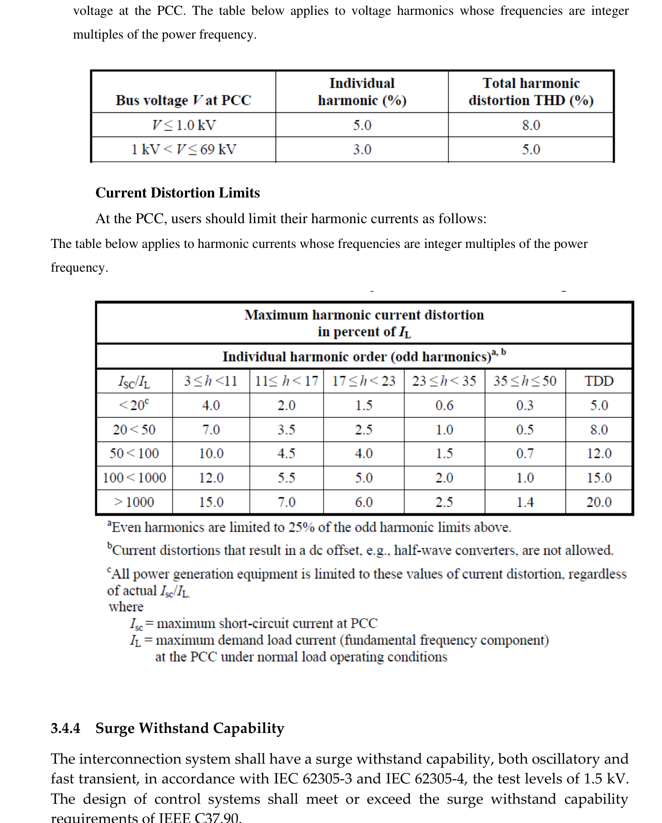
3.4.4 Surge Withstand Capability
The interconnection system shall have a surge withstand capability, both oscillatory and fast transient, in accordance with IEC 62305-3 and IEC 62305-4, at test levels of 1.5 kV. The design of control systems shall meet or exceed the surge withstand capability requirements of IEEE C37.90.
3.4.5 Voltage Unbalance
The total voltage unbalance in the grid should be smaller than 2%. The contribution from the MSDG installation may not cause an increase of voltage unbalance of more than 1.3%.
3.4.6 Voltage Step Change
Step voltage changes caused by the connection and disconnection of generating plants shall not exceed ±3% for infrequent planned switching events or outages and ±6% for unplanned outages such as faults. Where induction generators are used (e.g. fixed-speed wind turbines), they shall be fitted with “soft starters” to limit inrush currents to roughly the rated current level.
3.5 Power Factor
The power factor of the MSDG at normal operating conditions across the statutory range of nominal voltage shall be between 0.95 leading and 0.95 lagging.
3.6 Maintenance
3.6.1 Generation Forecast
Generators under 500 kW do not need to communicate a generation forecast to CEB.
3.6.2 Generation Maintenance
Generators under 500 kW do not need to communicate their maintenance plans to CEB for approval.
3.6.3 Network Maintenance
The MSDG owner shall disconnect their MSDG system during maintenance of the network by CEB. For preventive maintenance and corrective action, no compensation will be applied for the loss of generation. CEB will communicate their maintenance plans to MSDG clients in the same manner as general clients.
3.7 Safety, Isolation and Switching
3.7.1 Rules for Working on LV Grid
The safety of personnel working on the network shall comply with the “CEB T&D Safety Rules”, which are in compliance with the Occupational Safety and Health Act 2005. The following rules must be respected before working on the LV grid:
- The system must be made DEAD, isolated from all possible sources of supply, all switches locked in visibly open positions, tested on site, and short-circuited and earthed.
- The MSDG shall have a local means of isolation that disconnects all live conductors including the neutral. The producer shall not energise a de-energised CEB power circuit.
- Switches shall be installed to disable automatic or manual closing of interconnecting switches or breakers. These switches shall be accessible to CEB personnel to obtain the necessary safety requirements while CEB is working on associated equipment or lines.
- In all circumstances, manually operated switches must be capable of being secured in the ‘OFF’ isolating position, located at an easily accessible position in the producer’s installation.
- The Busbar System (Joint Use Facility) shall be accessible to CEB on a 24-hour basis for switching and isolation operations.
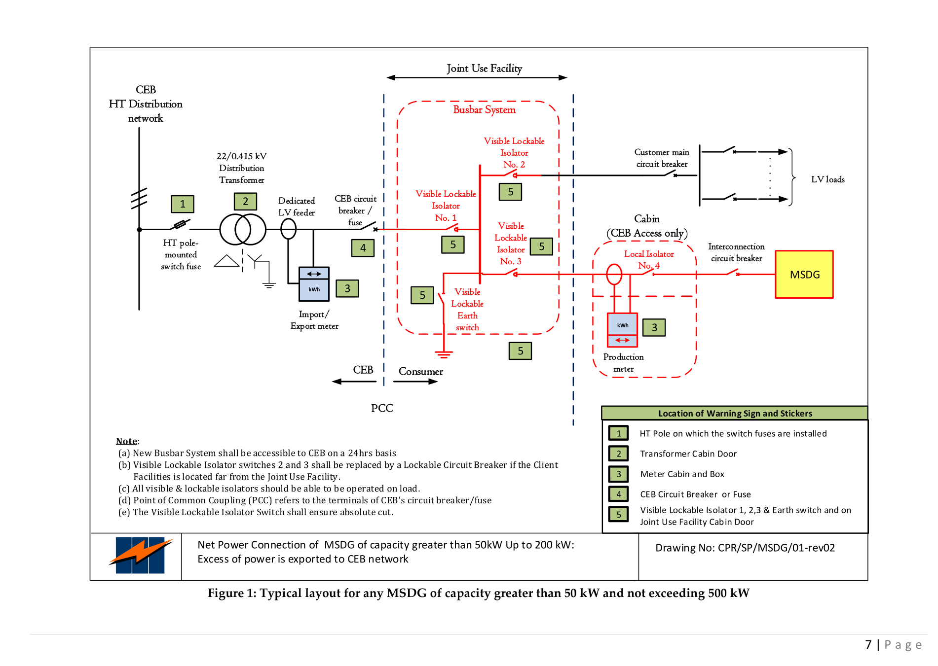
- All MSDG installations should be labelled with proper signage at appropriate locations as per Figure 1.
- The number and sequence of procedures shall be affixed in the Joint Use Facility and followed at all times to ensure correct switching operations during both the earthing of the busbar system and isolated generation setup.
- CEB will maintain an updated register of all MSDG installations with precise addresses, connection points and relevant transformers.
3.7.2 Safety Concerns
For any work or activity at the connection point between distributed generation and the CEB network, all agents involved will follow the “CEB T&D Safety Rules”. In addition:
- Persons must be warned that the installation includes an MSDG so that precautions can be taken to avoid electric shock. Both the mains supply and the electric generator must be securely isolated before electrical work is performed.
- PV cells produce output whenever exposed to light; wind turbines produce output whenever turning. Additional precautions such as covering PV cells or restraining the turbine are required when working on circuits close to the source of energy and upstream of the isolation point.
- The manufacturer or supplier of the MSDG must certify compliance with the Electrical Equipment Safety Regulations and the Electromagnetic Compatibility Regulations. The MSDG will be CE marked or tested by an equivalent accredited testing agency.
- Maintenance works at the MSDG installation shall be carried out following all safety procedures recommended by the manufacturer or supplier.
- CEB personnel must be warned of the safety procedures pertaining to switching operations applicable to the MSDG. These procedures must be clearly displayed and visible at the MSDG site.
3.7.3 Electromagnetic Emission / Immunity
The MSDG shall comply with the requirements of the EMC Directive and in particular the product family emission standards.
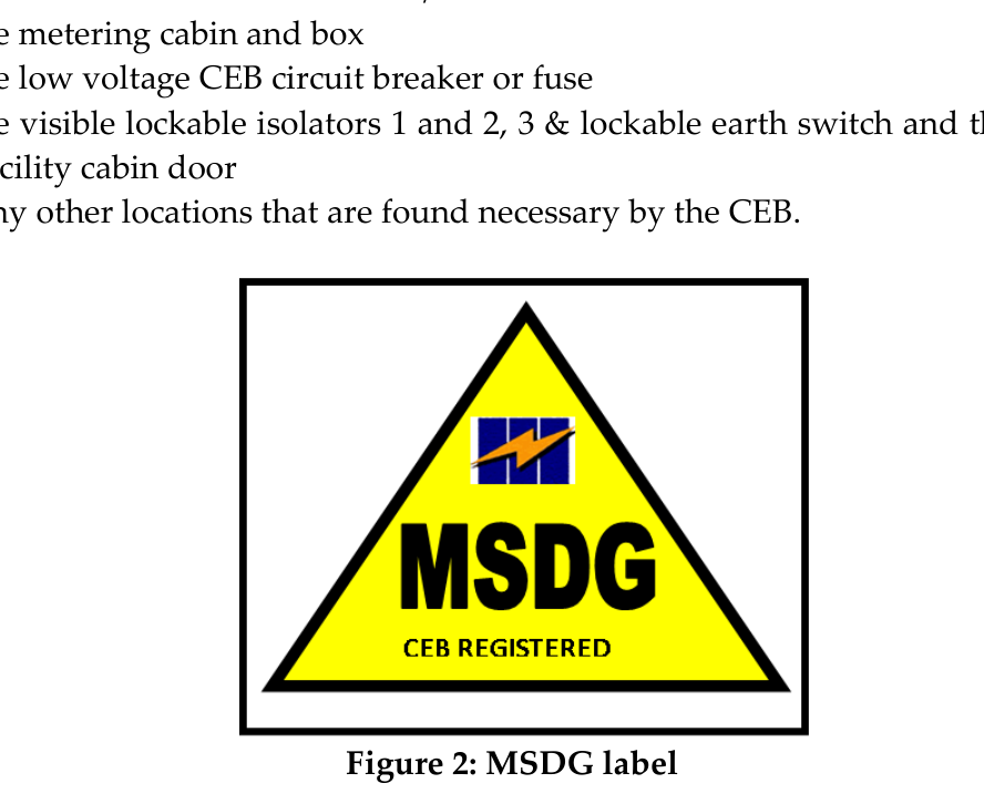
3.7.4 Labels
To indicate the presence of the MSDG within the premises, a label (as per Figure 2 below) will be fixed by the CEB at:
- The 22 kV pole on which the switch fuses are installed (or the Ring Main Unit in case of underground networks)
- The transformer cabin door and/or fence
- The metering cabin and box
- The low voltage CEB circuit breaker or fuse
- The visible lockable isolators 1, 2 and 3 & lockable earth switch and the Joint Use Facility cabin door
- Any other locations found necessary by the CEB
The installation operating instructions must contain the manufacturer’s contact details (name, telephone number and web address).
3.7.5 Documentation
Up-to-date information must be displayed at the MSDG as follows:
- A circuit diagram showing the relationship between the MSDG and the CEB’s circuit breaker/fused cut-out, and showing by whom the generator is owned and maintained (see Figure 3 below).
- A summary of the protection settings incorporated within the equipment.
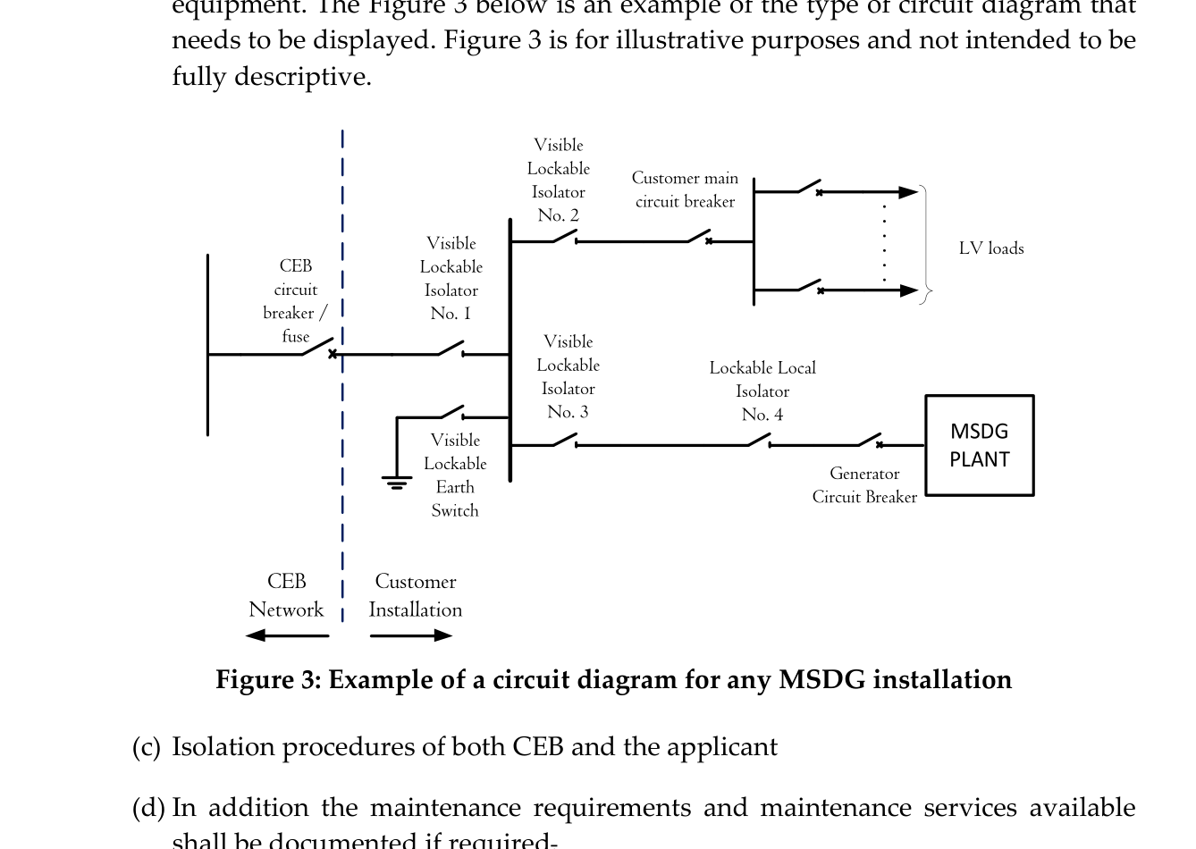
- Isolation procedures of both CEB and the applicant.
- In addition, the maintenance requirements and maintenance services available shall be documented if required.
- The MSDG Owner shall keep a certificate signed by the maintenance contractor containing at least the following: a statement confirming the solar PV/wind turbine/hydro meets requirements of this grid code; client’s name and address; site address; contractor’s name, address and contacts; list of key components installed; estimation of system performance; maintenance schedule.
3.7.6 Information Plate
The following information shall appear on the information plate: (a) manufacturer’s name or trade mark; (b) type designation or identification number; (c) rated power; (d) nominal voltage; (e) nominal frequency; (f) phases; (g) power factor.
3.7.7 Electrical Contractor / Installer
The MSDG shall be installed in accordance with the manufacturer’s instructions. In designing the connection, the installer must consider: maximum demand and generator output; type of earthing arrangement; nature of the supply; external influences; compatibility, maintainability and accessibility; protection against electric shock and thermal effects; protection against overcurrent; isolation and switching; selection and installation issues.
The installer must affix a label clearly indicating the next scheduled maintenance of the installation and inform CEB to update the MSDG register. The installer must be skilled in the field of MSDG installations and possess an MQA-approved qualification or equivalent in electrical installation and renewable energy installations acceptable to CEB.
3.8 Metering
A bidirectional meter measuring both the import and export energy shall be installed. Billing will depend on the applicable MSDG scheme. A second meter measuring the gross production of the MSDG shall also be installed (as shown in Figure 1). The power cable should fit in the inner diameter of the CT for the production meter, and CTs shall conform to IEC 61869-2 with sealing facilities.
The MSDG promoter shall first seek CEB’s approval prior to ordering CTs and VTs, and shall send same to CEB’s Meter Lab Section for tests prior to installation. Toroidal CTs will not be accepted for HT metering purposes.
In cases where it is not possible to locate the production meter next to the import/export meter, the production meter shall be equipped with a separate modem and SIM card. The cost of the additional modem and the monthly communication charge shall be charged to the applicant, as well as any faulty metering equipment in the future.
Both import/export and production meters shall primarily be CT-connected meters. The CTs used for the production meter shall have an independent core for metering with accuracy Class 1. All meters and related equipment (CT, TTB, etc.) shall be housed in a secured cabin as per CEB’s requirements, fitted with a 13A power socket protected by a 2A circuit breaker and fed from a secured source of supply.
3.9 Testing, Commissioning and Maintenance
Testing of MSDG installations will be done in the presence of CEB. The MSDG Owner shall notify CEB in advance with a testing and commissioning plan. The MSDG Owner shall keep written records of test results and protection settings. The MSDG Owner shall regularly maintain their protection systems in accordance with good electrical industry practice and any revision brought to this Grid Code.
3.10 Standards and Regulations
All electrical apparatus, materials and wiring supplied shall comply with the Electricity Act, the Central Electricity Board Act, Electricity Regulations, this code and the following standards (latest editions apply):
Table 4 — List of Standards
PV Modules
- IEC TS 62804-1 — PV modules: Test methods for detection of potential-induced degradation — Crystalline Silicon
- IEC TS 62804-2 — PV modules: Test methods for detection of potential-induced degradation — Thin-film
- EN 50380 — Datasheet and nameplate information of photovoltaic modules
- IEC 61215 — Crystalline silicon terrestrial PV modules — Design qualification and type approval
- IEC 61646 — Thin-film terrestrial PV modules — Design qualification and type approval
- IEC 61701 — Salt mist corrosion testing of PV modules
- IEC 61730 — PV module safety qualification
- IEC 61853-1 — PV module performance testing and energy rating — Part 1: Irradiance and temperature performance measurements and power rating
PV Inverters
- EN 50524 — Data sheet and name plate for photovoltaic inverters
- IEC 61683 — Photovoltaic systems — Power conditioners — Procedure for measuring efficiency
- IEC 62109 — Safety of power converters for use in photovoltaic power systems
- IEC 62116 — Test procedure for islanding prevention measures for utility-connected PV inverters
Grid-Connected PV Systems
- EN 50438 — Requirements for connection of micro-generating plants in parallel with public LV distribution networks
- ER G59/3 — Recommendations for connection of generating plant to distribution systems of licensed DNOs
- ER G83/2 — Recommendations for connection of type tested small-scale embedded generators (up to 16 A per phase)
- EN 50521 — Connectors for photovoltaic systems — Safety requirements and tests
- IEC 61727 — PV systems — Characteristics of the utility interface
- IEC 61836 — Solar PV energy systems — Terms, definitions and symbols
- IEC 62093 — Balance-of-system components for PV systems — Design qualification natural environments
- IEC 62446-1 — PV systems — Requirements for testing, documentation and maintenance — Part 1: Grid-connected systems
- IEC 60904-1 — Photovoltaic devices — Part 1: Measurement of PV current-voltage characteristics
- IEEE P1547 — Series of Standards for Interconnection of Distributed Resources
Wind Turbine Generators
- IEC 61400-21 — Wind Turbines — Part 21: Measurement and assessment of power quality characteristics of grid-connected wind turbines
General Engineering Standards
- BS 7354 — Code of Practice for Design of high voltage open-terminal stations
- BS 7430 — Code of Practice for Protective Earthing of electrical installations
- IEC 60068-2 — Environmental testing of specimen to withstand specific severities
- IEC 60076 — Power transformers — ALL PARTS
- IEC 60228 — Conductors of Insulated Cables
- IEC 60364-1 — Low-voltage electrical installations — Part 1: Fundamental principles, assessment of general characteristics, definitions
- IEC 60364-5-54 — Low-voltage electrical installations — Earthing arrangements and protective conductors
- IEC 60364-5-55 — Electrical installations of buildings — Selection and erection of electrical equipment — Other equipment
- IEC 60502-1 — Power Cables with extruded insulation for rated voltages from 1 kV up to 30 kV — Part 1: Cables for 1 kV and 3 kV
- IEC 60664-1 — Insulation coordination for equipment within low-voltage systems — Part 1: Principles, requirements and tests
- IEC TR 60909-1 — Short circuit currents in three-phase AC systems — Part 1: Factors for calculation
- IEC 62208 — General requirements for empty enclosures for LV switchgear and control gear assemblies
- IEC 62305-3 — Protection against lightning — Part 3: Physical damage and life hazard in structures
- IEC 62305-4 — Protection against lightning — Part 4: Electrical and electronic systems within structures
- IEEE C37.90 — Standard for Relays and Relay Systems Associated with Electric Power Apparatus
Power Quality
- IEC 61000-3-2 — EMC — Limits for harmonic current emissions (equipment input current ≤ 16 A per phase)
- IEC 61000-3-3 — EMC — Limitation of voltage changes, fluctuations and flicker — Equipment with rated current ≤ 16 A per phase
- IEC 61000-3-11 — EMC — Limitation of voltage changes, fluctuations and flicker — Equipment with rated current ≤ 75 A
- IEC TR 61000-3-7 — EMC — Assessment of emission limits for connection of fluctuating installations to MV, HV and EHV power systems
- IEC 61000-6-1 — EMC — Generic standards — Immunity for residential, commercial and light-industrial environments
- IEC 61000-6-3 — EMC — Generic standards — Emission standard for residential, commercial and light-industrial environments
- IEEE 519 — Recommended practice and requirements for harmonic control of electric power systems
- IEEE 1453 — Recommended Practice for the Analysis of Fluctuating Installations on Power Systems
Note: All specifications shall be according to the latest edition of the standards mentioned above. The MSDG owner shall also ensure that their proposed installations comply with all prevailing regulations pertaining to environment, health and safety.
Chapter 4 — Compliance with the Code
In case of non-compliance with any of the technical provisions in this Grid Code, CEB shall inform the owner in writing of the discrepancies. The MSDG owner shall have 90 days to rectify the discrepancies. Failing to do that, CEB shall be entitled to disconnect the MSDG installation.
CEB shall be entitled to disconnect the MSDG facility without prior notification if the installation conditions are harmful or create unavoidable risks for safety. CEB shall not be responsible for any damage if such disconnection requires the disconnection of other loads associated or connected to the same connection as the MSDG.
Reconnection of the MSDG shall require that CEB certifies that the installation complies with this Grid Code. Fees applicable shall be the same as the standard reconnection fees.
Annexes
Annex 1 — Abbreviations and Definitions
- “AC” or “a.c.” — Alternating Current
- “Applicant” — A producer of electricity through any MSDG installation
- “CEB” — Central Electricity Board
- “Circuit breaker” — A switching device capable of making, carrying, and breaking currents under normal and abnormal (e.g. short-circuit) conditions
- “DC” — Direct Current
- “DG” — Distributed Generation
- “Distributed generation” — Electric generation facilities connected to the Utility network at the PCC
- “Flicker” — A variation of input voltage sufficient in duration to allow visual observation of a change in electric light source intensity
- “Fault” — A physical condition that causes a device, component or element to fail to perform in a required manner (e.g. short-circuit, broken wire, intermittent connection)
- “Frequency” — The number of complete cycles of sinusoidal variation per unit time
- “Greenfield” — An installation of MSDG at a location without an existing connection point
- “Grid” — CEB’s network that brings electricity from power stations to consumers
- “Harmonic distortion” — Continuous distortion of the normal sine wave, typically caused by nonlinear loads or inverters; measured in Total Harmonic Distortion (THD)
- “HT” — High Tension (systems normally operating at voltage exceeding 1000 V AC or 1500 V DC)
- “HV” — High Voltage (see “HT”)
- “Installer” — A person skilled in the field of MSDG installations, possessing an MQA-approved qualification or equivalent in electrical installation and renewable energy installations acceptable to CEB
- “Islanding” — A condition in which a portion of the CEB’s network is energised by one or more MSDGs through their PCC(s) while electrically separated from the rest of the system
- “Isolated Generation” — A condition where the electrical path at the PCC is open and the MSDG continues to energise local loads
- “kV” — Kilovolt
- “kVA” — Kilovolt Ampere
- “kW” — Kilowatt (1,000 W)
- “kWh” — Kilowatt hour
- “LV” — Low Voltage (systems normally operating at voltage not exceeding 1000 V AC or 1500 V DC)
- “MSDG” — Medium Scale Distributed Generation
- “MW” — Megawatt (1,000,000 W)
- “Parallel operation” — A condition where the MSDG is operating while connected to CEB’s network
- “PCC” — Point of Common Coupling — the point at which an MSDG is connected to the CEB’s network
- “Power factor” — Ratio of real to total apparent power (kW/kVA)
- “Producer” — A producer of electricity through an MSDG installation or the owner thereof
- “PV” — Photovoltaic
- “RE” — Renewable Energy
- “Registered Professional Engineer” — A person registered as a Professional Engineer (Electrical or equivalent) under the Registered Professional Engineers Council Act (Mauritius)
- “SWC” — Surge Withstand Capability — the immunity of equipment to fast and repetitive electrical transients
- “TT system” — A TT earthing system where the protective earth connection of the consumer is provided by a local connection to earth
- “THD” — Total Harmonic Distortion
Annex 2 — CEB Fees
The MSDG will be connected to CEB’s 22 kV network through a dedicated 22/0.415 kV distribution transformer and metered on the low-voltage side as per the schematics shown in Figure 1 of this Code. In the absence of a dedicated transformer, CEB will consider applications on a case-to-case basis.
The applicant shall bear fees for processing applications and preparation of cost estimates for network construction or modification. The list of fees is available on the CEB website.
Annex 3 — Certificate of Installation
The applicant/installer shall submit a duly signed certificate with the company’s header and seal to the CEB. For HT Metering clients, the MSDG installation shall be certified by a Registered Professional Engineer (Electrical) (CRPE Mauritius).
The Certificate of Installation shall confirm:
- Installed capacity [kW] and site address
- Details of equipment installed (PV Modules, Inverter — make, model, rated output power, quantity, serial numbers)
- Inverter protection parameters and trip settings (Over Voltage × 2, Under Voltage, Over Frequency, Under Frequency, Loss of Mains df/dt & Vector shift, Reconnection Time, Active Power Limit)
- Line impedance (ohm)
- Name and signature of Installer company and Registered Professional Engineer / Installer (with RPEM No. if applicable)
- Name and signature of Applicant
- Seal of Installer Company and Date
Annex 4 — Certificate of Compliance
This certificate confirms that on [date] the MSDG installation with an installed capacity of [kWp], situated at [address] in the name of [Applicant/Company name] bearing Serial No. [MSDG/XX/XXX], has been found compliant with the requirements of the MSDG Grid Code (50 kW to 500 kW) by CEB representatives and is fit for connection to the Grid. The installation shall be commissioned after the signature of the Connection Agreement.
The Certificate of Compliance is signed by representatives from:
- Distribution Network
- Meter Installation
- MSDG Unit
- Safety and Health Section
Annex 5 — Capping Certificate
A Capping Certificate shall be completed and signed by the installer company upon capping of the MSDG installation, confirming that the capacity capping has been applied to the installation in accordance with CEB’s requirements. The certificate shall include:
- Name of Installer Company
- Name of Registered Professional Engineer / Certified Installer and RPEM No. (if applicable)
- Signature, Date and Seal of Installer Company
- Name and Signature of Applicant and Date